Solutions
- Home
- Solutions
eDIDIO Configurator DALI Line Summary (Real-time)
DALI Commissioning
Using our eDIDIO controller the DALI line can be quickly and easily commissioned over any network. The device scan takes half the time of our leading competitors[1], and allows for instant viewing of each device. This is available in our free configuration software when you have a device connected.
[1] Tested with 18 DALI devices (Above – 17.8 seconds, Competitor Test – 44.6 seconds)
Custom solutions
Do you have that 1 light in a project using a different protocol? Do you need a device which does not exist? Creative Lighting provide many, many, many solutions. If you are after a custom project solution, chances are we have done it before. Just to name a few;
DMX to DALI (With RDM Selectable features)
Potentiometer to DALI/DMX Level/Scene/Pulse
0-10V to DALI, DALI to 0-10V
DMX to Output (24Vdc Isolated/5V)
DALI to Output (24Vdc Isolated/5V)
DALI T8 Circadian Sequencer
DMX Splitter as a “DMX Diode” to prioritise house DMX Desks
DMX Detection to Output/Ethernet/Serial
Long DALI Fade times (170 minute fades)
18 Channel Constant Voltage LED Drivers
144 Channel Constant Current LED Driver
WHAT IS DALI?
DALI is not a product. It is on open protocol, an interface between DALI devices and controllers and is perhaps more properly known as IEC 62386, which is published by the International Electrical Commission. As such, it is an international Standard for digital control of lighting and other electrical devices. DALI is an acronym for the Digital Addressable Lighting Interface.
A key feature of DALI is that the open platform it provides allows seamless interoperability between numerous manufacturer’s DALI-compliant products.
DALI devices can have unique identifiers called a short address. The list of DALI devices includes dimmable fluorescent, compact fluorescent, and halogen lamps (via DALI transformers), LED dimmers and sequencers, DALI-switched HID luminaires, dimmers, fans, motors, et cetera.
Creative Lighting designs and manufactures DALI, DMX512-A and RDM compliant products, and has extensive award-winning lighting and electronics design and engineering experience. As a result of all this experience, we can pass on a few useful tips to those contemplating a role in realising a DALI project, including tips for specifiers engineers and designers; tips for installers and tips for systems integrators.
DALI Addressing
In 2004 Creative Lighting released the first of its DALI tools, the ADDICT (which is now at Version 3).
Among the many innovations pioneered by the ADDICT is its binary search algorithm for addressing DALI devices. This algorithm has been used a great many times over the past ten years by systems integrators, installers, manufacturers and maintenance personnel all over the world*, to assign short addresses to DALI devices. Our binary search works by simply searching for a single long address to assign to a short address and it does so by halving the set of all the long addresses of all connected devices. If more than one device is in the first half sub-set, the algorithm will look for a single device reply in the other half subset. When the first single device is found it will be assigned short address 0, with subsequent single devices found being assigned 1, 2, 3 and so on. The search will continue to halve subsets until a single device is found in any sub-set. The discovery of a single device in a subset will result in a short address being assigned to that device and the algorithm then branching to search the other branch subset and so on, until both halves of a subset have no single device in them whereupon the algorithm will terminate the short addressing process. The assignment of a short address will be indicated automatically by the ADDICT instructing that device to illuminate or otherwise identify itself when it is successfully addressed, however this feature can also be disabled by turning off “Live Preview” mode.
We have now released FlitR as an alternative addressing method which does not use our binary search for long or short addresses, but instead uses our new outer loop / inner loop search algorithm. FlitR can be used with smartphones and tablets over wifi and is fun and very fast. It works with DALI and RDM and can be used for other protocols as well. It is patent pending and simply requires our new eDIDIO controller and our matching app for Android. Of course, for all other DALI work including sniffing, powering, settings and more the ADDICT is still the professionals choice. The V2 eDIDIO offers a free random addressing using our original binary search, which can then be remapped using FlitR. Licencing of FlitR is available for 3rd party manufacturers to include in their products.
* ADDICTs are located from as far south as the Antarctic to as far north as Sweden. There are ADDICTs on most continents including Europe, Americas, Australia, Africa and Asia.
Specifier Tips
1. Lamps & lamp life, 2. DALI lines, 3. Drawings & Documentation, 4. Dali Products (Cabling, Brands, Power Supplies, Recommended) 5. Saving energy & avoiding complaints: occupancy sensors & daylight harvesting. 6. Operator training and maintenance including backing up device settings.
1. Lamps
a) All major types of fluorescent lamp sources can be dimmed BUT they must be first run in by powering on at 100% for a minimum of 100 hours / 4 days, or you are unlikely to achieve the rated lamp life.
b) The life of fluorescent lamps is usually based upon switching duty cycles. You should mitigate the use of regular power cycling or short lamp life may result. Dimming up and down from as low as 1% to as much as 100% is generally considered to have no negative impact on life expectancy, once the lamps are run in. Control Freak DIDIOs can have automatic 100 hour burn-in facilities on request.
2. DALI line (previously also called ‘loop’ or ‘bus’)
The 64 device maximum per DALI line is just that: a maximum. A good rule of thumb is to allow no more than around 50 devices (addresses) per line, to allow flexibility to rework DALI lines down the track and add more DALI devices to lines, eg for future tenancy changes. Note that controllers and many peripherals (such as daylight and occupancy sensors and push button plates) are not assigned DALI addresses and therefore do not impact on the 64 device maximum. If the peripherals draw their power from the DALI, you need only ensure that the DALI power supply has sufficient current for them. Most brands of DALI ballasts for example draw <2ma each and are generally either 1watt or 0.5watt in standby (lamp is off but power on to the ballast. The term ‘loop’ was previously used in the DALI Standard because DALI is bi-directional. A data ‘loop’ is NOT a closed wiring circuit – the data cabling must be terminated into the controller at only one end of the cabling run, hence the move to change the term ‘loop’ to ‘line’.
3. Drawings & documentation
Mark the DALI addresses on your plans next to the symbol for each DALI device. The addresses should be in a logical order – eg all lights within a given room to have consecutive DALI addresses. There are a number of reasons for this and first among them is the need to quickly identify the location for a light that has reported a lamp failure. If you choose not to label the DALI lights with their addresses, you should at a minimum require the contractor to provide as-installed drawings that are labelled with the DALI addresses (and groups) for hand-over to the client.
Incorporate BIT and CDL Procedural Statements in your written Specifications (with an appropriate acknowledgement of the author please) to clarify the scope of works to be done by the electrical contractor and/or systems integrator.
4. Products & components
a) Cabling
The DALI standard requires a minimum conductor size of 1mm2 and a maximum voltage drop of 2VDC and cabling for the DALI should therefore be sized to suit. DALI is a two wire system, requiring mains-rated cabling, and has no polarity sensitivity. Many projects opt to use 5 core soft wiring and connectors (L, N & E plus DALI) which can save significantly on installation time and make tenancy changes in the future quicker and cheaper.
It is generally recommended that DALI cabling is not less than 150mm away from high current and three phase AC cabling to avoid interference.
Supply total
Maximum number of devices
Maximum run length
Maximum Aggregate run length
245mA (DIDIO) 21vdc
64 individually addressed
AWG18
1mm2
170m
AWG16
1.3mm2
265m
AWG14
1.6mm2
425m
AWG12
2mm2
670m
b) Mixing brands
The intent of the DALI standard is that compliant devices will work perfectly well with other DALI devices from any manufacturer. So you not only can mix brands, it is essential for all DALI devices to work together. If a manufacturer tells you that you must use their DALI peripherals (controllers, sensors, power supplies, etc) with their DALI devices (ballasts, motor controllers, etc), read the previous sentence again.
c) Selecting power supplies
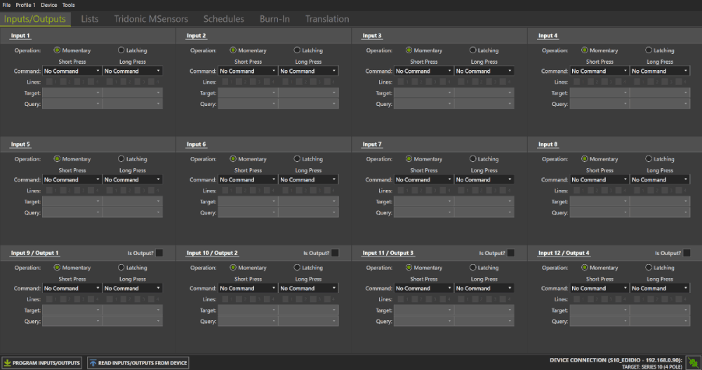
Devices ‘talk’ by shorting the DALI line, to the DALI specified maximum current of 250mA. You should NOT combine/parallel dc power supplies for DALI, so select a power supply that is as close as possible to the maximum shorting current of 250mA, particularly when using a lot of devices that draw their power from the line, and to allow for future changes and additions to the DALI. For example, at time of writing, the DIDIO and UBi Power power supplies are rated at 245mA. Many other makes are rated below 200mA. A key feature of the DIDIO is that is not only a Power Supply for the line, it is also both a Serial Communications Interface and a Scene Controller, all in one DIN mount package. The DIDIO allows the specifier to have a simple pushbutton control panel at the switchboard, for emergency overrides and maintenance scenes. The pushbutton panel can comprise standard momentary bell press mechanisms and can be equipped with up to 12 buttons, each of which will initiate a different DALI Scene, for Scenes 1 to 12 respectively on each DALI line (each DIDIO is designed to control and power one DALI line only).
5. Saving energy and avoiding complaints
There are three main approaches to automatic control that will save energy with DALI: Occupancy Sensing, Daylight Harvesting, and Operator Training/Maintenance.
a) Occupancy sensing
A successful occupancy sensing system will automatically fade lights down in a given area – and do so slowly enough for people to exit the area – and then turn the lighting off if there is still no one present in that area (or brighten if people re-enter).
The main component to occupancy sensing is of course the motion sensors themselves. There are a plethora of sensors on the market, and in general those made by the security industry offer the biggest choice and many of the most reliable sensors at reasonable cost. Select sensors that are designed for the environment you intend to use them in. If you elect to use a standard security sensor, select ones that have a Normally Open (NO) setting and specify the NO setting for best results. The controller you select – such as the Control Freak DIDIO – should be capable of running timers initiated by motion sensors, preferably with a warning period during which the lighting will hold at minimum light levels for a couple of minutes before turning the lights in that area off.
b) Daylight harvesting
Daylight ingress can be a good thing, and it makes sense to reduce artificial lighting levels (and energy) when there is adequate daylight. However, implementing daylight harvesting should be approached with caution.
For example, consider a typical building in which the only daylight ingress is through the verticals eg windows/curtain wall glazing. If there is an unobstructed view of daylight illuminated surfaces (for example an exterior building wall), the internal spaces further into the building may appear gloomy, even if the actual lighting levels meet code. This occurs because normal human vision will automatically adjust to the brighter surface (in this case the external day lit surface) and, as a consequence, the brightness of the rest of the field will appear to be relatively lower – in this case, gloomy.
Then there is the situation of the worker whose desk is closest to the source of daylight ingress. In a well planned control system, that worker’s lighting will be dimmer than that of a colleague sitting at a desk deeper into the building (away from the daylight source). Whilst the actual light levels on both desks may be comparable, the perception of reduced lighting may give rise to complaint from the worker with the dimmer lighting because his overhead lighting is obviously operating at a dimmer level.
Then there are the daylight sensors themselves, and these are often simple photo-dependant resistors or circuits, with an adjustable iris. They are generally oriented to face downwards so that they mainly ‘read’ reflected light, usually off a desk. This type of sensor has the advantage of being inexpensive and simple but they have no settings that relate to an empirical measurement such as illuminance and they typically drive the DALI device’s ballast directly without using DALI commands. One pitfall with this type of device is that a bright surface moved beneath them (even a bald head) can cause the sensor to ‘see’ more light and so reduce the illumination of the lighting to which it is connected. Covering highly reflective surfaces with dark materials may also cause the light levels to change.
A good control system will track the changes in the lights which have such sensors attached, and will use that information together with site information to automatically adjust appropriate lighting around it, and to a lesser degree the lights deeper into the building. In addition, a good control system will avoid ‘hunting’ which can occur with passing clouds for example.
Regardless of the control system however, if the sensor is not a DALI device, the light it is attached to cannot be controlled by DALI successfully except to either turn it off with a DALI off command or send it on – it will effectively be operating independently. It nonetheless can be monitored by the selected control system.
6. Operator training and maintenance
It is good practice to specify the use of a purpose-built tool for the commissioning of the project such as the ADDICT-sys, and the handover of that tool at the end of the project as an essential part of the training of operators and maintenance staff.
In addition, the ADDICT is capable of backing up the settings of all DALI devices on each DALI line, so that future replacement of the devices can simply reload the device settings to match the addresses of the new devices with those of the replaced devices.
The settings in a standard DALI device include being added to or excluded from any of up to 16 Groups, being part of or excluded from up to 16 scenes at programmable intensity levels including mask (which is used for devices that should take no action in that scene), fade times, fade rates, system failure level (loss of DALI), power on level, Minimum levels and Maximum levels; and all these settings may vary from device to device. Specifying that all devices are backed up to suitably named computer files for later retrieval is a sensible precaution to the eventual need to replace DALI devices and avoid unnecessary reprogramming costs.
Install Tips
BIT: Basic Installation Testing
by Lance Stewart, Creative Lighting
The job for installers, typically electrical contractors, is to install, wire and prove out the DALI lines and DALI devices before handing over to a Systems Integrator (although some firms also do the integration).
To ‘do your BIT’, these are the 5 simple steps to take:
The first stage of BIT requires no special tools (a multimeter and some hand tools only) and its as easy as 1,2,3!
BIT 1 – Lights work, BIT 2- DALI cables voltage-free, BIT 3- DALI cables OK,
The second stage of BIT requires a DALI tool, such as an ADDICT (eg the -eco model which is very quick and easy to use)
BIT 4-All lights receiving, BIT 5- All lights replying & addressed
BIT 1) Lamps On. With mains power to all DALI luminaires, ensure that all lamps are on and working. If not, remedy. If ok, go to BIT 2.
BIT 2) Test the free ends of the DALI wiring and certify that they are free of power. At this stage the only devices connected to the DALI lines should be receivers eg luminaires and the like. Do not connect controllers and power supplies. If the DALI lines have power, remedy then repeat BIT 2. When the lines are voltage-free, go to BIT 3.
BIT 3) Turn on (or power) each DALI line’s power supply and test the starting voltage (which is the power supply’s output). The so-called ‘high levels’ (when nothing is communicating) for DALI are: nominally 16v dc, minimum 9.5v dc, maximum 22.5v dc. Check the rating on the power supply you are connecting to the line, then test that the output matches the rating. (For example, Creative Lighting DIDIO PS is ~22v dc). Then connect the power supply to the DALI line and go to the end of the line and test the voltage there. If the voltage at the end of each line is not within 2v dc of the starting voltage at the power supply, you have a drain on the DALI cabling which you should identify and remedy.
BIT 4) Do not start Bit 4 until all fluorescent and compact fluorescent lamps are run in (run at full intensity for 100 hours before they are dimmed) or lamp life will degrade significantly.
Do not connect DALI controllers yet. If the DALI power supplies cannot be on without the controllers also being on, disconnect the controllers.
Using a suitable DALI tool (eg a Control Freak ADDICT), test the line with a continuous MIN/MAX command which will cause all connected lights on the line to repeatedly fade up and down in a continuous cycle. (Note that an externally powered ADDICT will supply power to the DALI line if no power supply is present.) Visually check that all lights on the line fade up and down. At the same time, check that no additional lights fade up and down – remember you MUST NOT exceed 64 devices on the line: we recommend 63 or less (to allow a spare address during remapping), and preferably 50 or so (to allow for future changes).
If ok, go to BIT 5, otherwise remedy and repeat BIT 4.
BIT 5) Using a suitable DALI tool (eg a Control Freak ADDICT), randomly address all devices on the line. Refer to your project documentation and compare the number of devices that are addressed by this method, compared with the expected number of devices (addresses) on the line being tested. If the numbers do not match, either use the DALI tool to find and remedy the addresses that are missing, or hand over to the project’s Systems Integrator for them to identify the fault during commissioning (you will later need to replace any device identified as faulty). If it is ok, connect the controllers to the lines and then – congratulations! You have done your BIT!